![]()
|
|
|
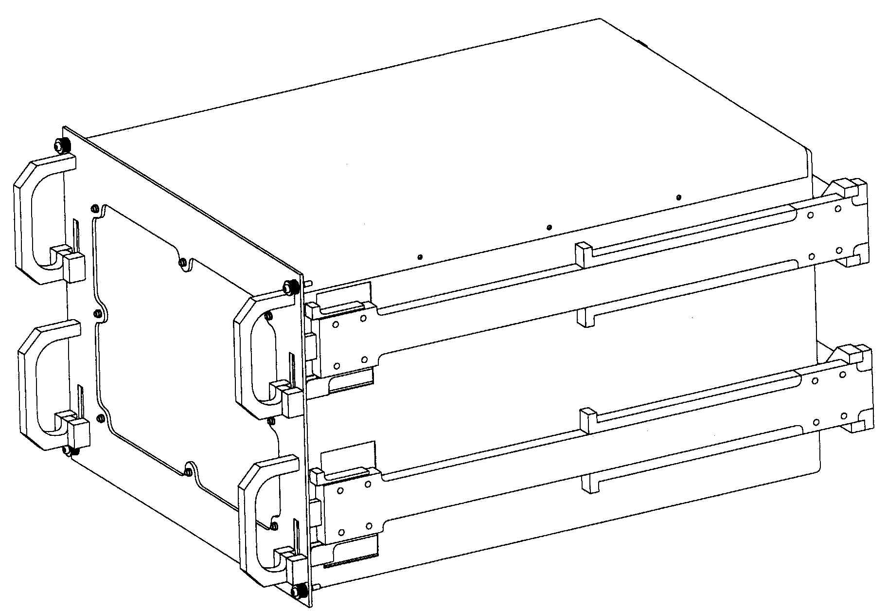
![]() The European Drawer Rack
(EDR)
The European Drawer Rack
(EDR)
The European Drawer Rack (EDR) is an infrastructure capable of supporting as much as 8 experiment dedicated payloads accommodated in Standard European Drawers (SED) or in Middeck Lockers (MDL). A total of four SEDs and four MDLs can be supported by the EDR. These have access to a number of centralised services that range from the distribution of system resources (e.g. venting, cooling etc.) to dynamic resource management, e.g. for simultaneous access to system resources by more than one payload.
Therefore, the EDR can support research and development experiments in the fields of Microgravity Sciences, Technology and Fundamental Physics.
It is foreseen that the wide diversity of payloads that make use of the EDR will be reflected in terms of system resources requirements (e.g. control of the experiment execution, data processing etc.).
Four different modes of operation will be made available to operate these Experiments: AUTOMATIC/AUTONOMOUS, ASSISTED AUTONOMY, MANUAL or TELESCIENCE.
The facility is configurable in flight. The experiments – accommodated in SEDs or MDLs - can be exchanged in orbit, and the EDR application software can be reconfigured accordingly.
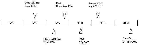
The EDR including a first set of drawers and lockers will be launched with the Columbus Laboratory in the time period 2002-2003.

The centralised services and sub-systems described below are accessible to all payloads. Specific rack locations are indicated where only a limited set of resources is available.
The Columbus Laboratory resources are provided to the EDR through the Utility Distribution Panel (UDP).
Facility General Capabilities
The following capabilities are provided:
|
The EDR is designed to allow standard payload integration with a minimum lead time (3 to 6 months). | |
|
Exchange of payloads does not require tilting of the rack in orbit. | |
|
Active Payloads extending beyond the rack front face are allowed during nominal operations (e.g. glovebox). | |
|
The Racks provides the capability to accommodate drawers from the Mini Pressurized Logistics Module (MPLM) transport rack, so that essential mechanical interfaces are compatible. | |
|
The EDR design provides mechanical interfaces for Standard European Drawers (SEDs) and Middeck Lockers (MDLs) that are compatible with the transportation racks of the MPLM installed in the cargo bay of the Shuttle for ISS re-supply missions. | |
|
The EDR design enables in-orbit resource re-configuration to support changes to payload operations. | |
|
The EDR design enables in-orbit exchange of payload drawers and middeck lockers. |
The EDR baseline consists of the following sub-systems:
|
ISPR rack, power, data, video and thermal subsystems | |
|
4 Standard European Drawers (SED) | |
|
4 Middeck Lockers (MDL) |
The SED/MDL payload interfaces are:
|
structure | |
|
rails | |
|
connectors, harness and piping | |
|
front panel with UDP quick disconnects and connectors | |
|
water cooled cold plates | |
|
air ducts |
The EDR resources are:
|
Data management (including an ethernet HUB) | |
|
Laptop | |
|
Power | |
|
Video | |
|
Air cooling | |
|
Water cooling | |
|
Nitrogen | |
|
Vacuum, venting | |
|
Smoke detection |
Laptop
An EDR configured laptop runs the specific software and display the desired human computer interfaces necessary to fulfil the tasks listed below:
|
Provide a common ‘look-and-feel’ human computer interface for the EDR facility control and for the experiments. | |
|
Run application software to control/monitor EDR payloads in assisted and autonomous mode via the facility controller. | |
|
Run the application software necessary for controlling the experiment in manual mode. | |
|
Run the software necessary for EDR facility operations and maintenance. | |
|
Display the video coming from the payloads, connecting to the Video controller. |
Power
EDR provides:
|
28 V DC (*) to each of the four SEDs (via rear connector). | |
|
28 V DC to each of the four MDLs (via front panel). | |
|
120 V DC to each of the four SEDs (*) (via rear connector). | |
|
120 V DC auxiliary power to one specific SED (via rear connector) |
For the 28 V DC outlets EDR
provides 5 and 10 Amps (140 and 280 Watts).
For the 120 V DC outlets EDR provides 3 Amps (360 Watts maximum).
The total power envelope is limited by the selected cooling capacity which is 1200 Watt for payloads if only air cooling is used and 2000 Watts is water cooling is used.
(*) During the course of the EDR project it may be decided that SEDs will be configurable either for 28 V DC or 120 V DC power supply.
Video
The Video Management Unit (VMU) will handle the analogue (NTSC) and digital image signals from the payloads (maximum 8) located in SEDs and MDLs. This includes the possibility for switching and/or multiplexing between different payload camera sources, intermediate digital storage on hard disk. Standard compression techniques (factor 2 to 20) will allow for a significant extension of the recording time. Higher compression factors will also allow for a qualitative observation in real time on ground (telescience/teleoperation). By using telecommands from ground it will be possible to adapt the frame rate and compression rate.
Overall VMU Characteristics:
|
Camera per SED/MDL payload |
One digital camera source and/or one analogue (NTSC) camera source |
|
Digital camera formats |
configurable to 512 x 512 or 1024 x 1024 pixels (each 8 bit) |
|
High data rate interface to SED/MDL |
configured digital camera interface |
|
Camera multiplexing |
4 cameras can be multiplexed |
|
Downlink capacity |
2 Mbit/s average (current limitation) |
|
Recording capacity (hard disk) |
16 Gbytes |
|
Recording time (1 camera) for 512 x 512 x 8 x 30 = 60 Mbit/s for uncompressed video: 16 Gbytes / 60 Mbit/s |
ca. 35 min (Example) |
|
Video (or high data rate) data format |
CCSDS bitstream |
|
Compression Standard |
JPEG with an adaptable frame and compression rate (current baseline) |
|
Telescience |
Image data reduction will be adapted to qualitative needs. Due to the characteristics of the human eye (time resolution approx. 70ms), the max. frame rate for telescience can be limited to 15 Hz. (frame rate 15/s) |
|
Telescience Downlink capacity (1 camera) for 512 x 512 x 8 x 15 = 30 Mbit/s for compression with factor 30.
|
1 Mbit/s (Example) |
Thermal Interface:
EDR will provide heat rejection capability at all payload locations as follows:
|
Air cooling per MDL and SED will be 400 Watts maximum with internal payload fan and 350 Watt if no internal payload fan is used. | |
|
Water cooling per MDL and SED will be 500 Watt maximum. |
The overall EDR heat rejection capacity is 2000 Watt if water cooling is used and 1200 Watts if air cooling is used.
Fire Detection and Prevention:
Two levels of Fire Detection and Prevention will be applied:
|
On rack level a SSD (Standard Smoke Sensor) is used for fire detection in combination with the AAA (Air Avionics Assembly). | |
|
On payload level with closed compartments (SED and MDL) additional parameter monitoring will be performed by the EDR controller for fire prevention. |
SED/MDL Interfaces
The European Drawer Rack (EDR) provides services to payloads contained in Standard European Drawers (SEDs) and in Middeck Lockers (MDLs).
|
EDR Characteristics |
SED |
MDL |
|
Number in baseline per SED/MDL |
4 |
4 |
|
Volume available to user per SED/MDL |
72 litres |
57 litres |
|
Mass available to users |
48 kg |
26 kg |
|
Heat rejection capability (1) - air cooling |
350 Watt (w/o payload fan) |
350 Watt (w/o payload fan) |
|
per SED/MDL - air cooling |
400 Watt (with payload fan) |
400 Watt (with payload fan) |
|
- water cooling |
500 Watt |
500 Watt |
|
Resources available to each user: |
Via rear connector |
Via UDP cable(s) to MDL front |
|
- Main power 28 V DC (5 and 10 Amps) |
1 per SED (2) |
1 per MDL |
|
- Main power 120 V DC (3 Amps) |
1 per SED (2) |
N/A |
|
- Auxiliary power 120 V DC (3 Amps) |
1 (one selected SED only) |
N/A |
|
- Analogue video NTSC RS 170A |
1 per SED |
1 per MDL |
|
- Digital video or high data rate (3) |
1 per SED |
1 per MDL |
|
- Data RS422 |
1 per SED |
1 per MDL |
|
- Data IEEE 802.3 (Ethernet) |
1 per SED |
1 per MDL |
|
- Discrete Input |
2 per SED |
2 per MDL |
|
- Discrete Output |
2 per SED |
2 per MDL |
|
- Analogue Input |
2 per SED |
2 per MDL |
|
Common resources: - Water cooling (4) |
Via UDP |
Via UDP |
|
- Gaseous Nitrogen (4) |
Via UDP |
Via UDP |
|
- Vacuum (venting) (4) |
Via UDP |
Via UDP |
Note:
The maximum rack cooling capability for air cooling is up to 1200 Watt, for water cooling up to 2000 Watt. A combination of both types of cooling is possible provided that the individual cooling capacity is not exceeded and the overall capacity of 2000 Watt is not exceeded.
SEDs will be configurable either for 28 V DC or for 120 V DC.
This connection can be configured as follows:
as digital video cameras (e.g. with 512 x 512 pixels or 1024 x 1024 pixels) or
as high data rate connection e.g. for users who have their own video processing such as PCDF (ESA’s Protein Crystallisation Diagnostics Facility).
The fluid utilities are accessible on the EDR UDPs (Utility Distribution Panels). The interfaces may be shared among the different P/Ls.
The following drawing features the basic design of the Standard European Drawer (SED)
This schematic provides some details of the structure and dimensions (in inches) of a Middeck Locker
Operations Capabilities
The following modes of payload operation are supported:
AUTOMATIC/AUTONOMOUS, i.e. no intervention from either the ground or the laptop.
ASSISTED AUTONOMY, i.e. using "breakpoints", which require intervention from the crew/ground. In other words the "science data gathering" is carried out autonomously under the supervision of the on-board or ground crew.
MANUAL by the crew. Control and monitoring are local to the SED and/or MDL , i.e. the laptop attached to the front panel. The facility controller and therefore the ground can only monitor through the TM stream or the video channel.
TELESCIENCE, i.e. experiment "interactively" controlled from the PI on ground. This implies that the responsibility for the experiment control is with the ground scientific team. It does not necessarily imply full availability of video downlink.
EDR Project Timeline
|
Page
reference: 32 |
|